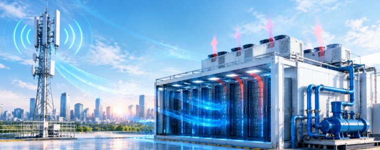



Cold plate cooling data center systems have become the default thermal strategy for AI workloads because they remove 70–80% of chip heat at the source, cutting PUE from 1.6 to 1.10–1.20 while enabling 50–100kW racks air cannot cool. This article dives into one detail that decides success: the microchannel cold plate and its coolant loop. You will learn the numbers that matter, the failure modes to avoid, and a phased deployment roadmap.
AI workloads pushed rack density from a 2022 average of 10kW toward 100–120kW by 2025, and hyperscalers now design more than 55% of new racks for liquid from the outset. Cold plate systems dominate these deployments because they fit existing server form factors and standard racks, unlike immersion tanks that demand purpose-built halls.
Why Has Cold Plate Cooling Become the Default for AI Data Centers?
NVIDIA Blackwell GB200 and AMD Instinct MI300X accelerators now draw 700–1,200W of thermal design power, breaching the physical wall of air cooling. Air is a weak conductor, while liquid transfers heat over 3,000 times more effectively. Cold plate cooling, also called direct-to-chip cooling, captured 42–48% of the liquid cooling market in 2025 and leads brownfield retrofits.
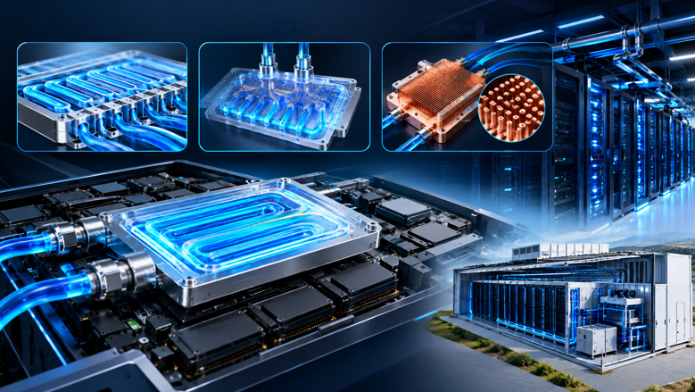
Cold plates bolt directly onto CPU and GPU packages in a cold plate cooling data center, replacing finned heatsinks. Coolant circulates through internal microchannels and absorbs heat at the silicon surface. This direct contact removes five of seven thermal interfaces found in air-cooled designs, shrinking required temperature differentials by roughly 75% and allowing warmer facility setpoints.
Air cooling hits a hard ceiling near 30–40kW per rack. A fully populated eight-GPU DGX-class server alone generates 10–15kW of heat from processors, and the NVIDIA GB200 NVL72 rack reaches 120kW. Beyond that ceiling, fans consume disproportionate power and chips throttle, which is why the thermal wall forced the industry toward cold plate cooling data center adoption.
How Do Microchannel Geometries Determine Cold Plate Cooling Data Center Performance?
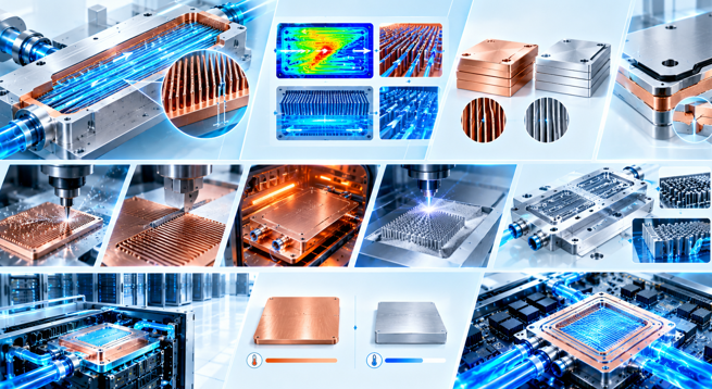
In a cold plate cooling data center, the microchannel pattern sets the ceiling for heat removal. Copper plates with skived or CNC-machined channels as narrow as 0.1mm achieve heat-transfer coefficients of 5,000–50,000 W/m²K, versus 50–250 W/m²K for air heatsinks. Denser channel arrays increase contact area by up to 35% and force turbulent flow that breaks the thermal boundary layer.
Material selection matters equally in a cold plate cooling data center. Pure copper offers the best conductivity for high-heat GPUs, while aluminum balances cost for lower-density CPUs. Manufacturers use friction stir welding or vacuum brazing to join covers without solder voids. A 0.08°C/W aluminum plate may satisfy 300W parts, but a 1,200W accelerator demands a copper plate near 0.04°C/W.
Manufacturing technique shapes performance. Skived channels trade precision for cost, CNC machining offers tight tolerances, and vacuum-brazed copper assemblies handle high pressure. Emerging designs use 3D printing to create pin fins and jet impingement structures that target GPU hot spots directly, achieving heat fluxes above 600 W/cm² in laboratory tests.
What Thermal Resistance and Heat-Transfer Numbers Actually Matter in a Cold Plate Cooling Data Center?
Thermal resistance, measured in °C/W, is the metric engineers compare first. Cold plate cooling data center components reach 0.02–0.10°C/W, while air-cooled heatsinks sit at 0.5–2.0°C/W—a 10–20x improvement. Lower resistance means a 700W GPU rises only about 5°C above coolant temperature, preventing thermal throttling that silently cuts training throughput.
Real deployments validate the physics of cold plate cooling data center design. CoolIT Systems kept 300 NVIDIA H100 GPUs at 62°C junction temperature using 25°C inlet water. Supermicro cold plates hold GPU cores below 75°C even with 32°C coolant inlet. By reducing chip temperatures by up to 20°C versus air, these systems let AI clusters sustain turbo clocks and shorten large language model training cycles.
PUE gains follow directly. Traditional air-cooled facilities operate at 1.4–1.6, while cold plate deployments report 1.05–1.20. Inspur’s cold-plate platform achieves PUE below 1.15, and a Beijing retrofit dropped from 1.48 to under 1.19. Every 0.1 PUE improvement on a 100MW campus can save tens of millions of dollars in annual power costs.
Standards now codify these numbers. ASHRAE TC 9.9 defines W1–W5 water temperature classes for liquid cooling, and the Open Compute Project publishes cold plate specifications that hyperscalers require. The EU Energy Efficiency Directive and Germany’s 2025 Data Center Energy Efficiency Act push new facilities below 1.2 PUE, making cold plate cooling a compliance tool, not just an efficiency upgrade.
Which Coolant and Flow Rate Keep a Cold Plate Cooling Data Center Loop Reliable?
Water-glycol mixtures dominate single-phase loops because water’s specific heat, 4.18 kJ/kg·K, is roughly four times air’s 1.01 kJ/kg·K. A typical GPU consumes only 0.5–1.0 liters per minute, replacing 200 CFM of fan airflow. Demineralized water or propylene glycol solutions protect copper, aluminum, brass, and steel from galvanic corrosion.
Water quality is non-negotiable in any cold plate cooling data center. Filtration down to 25 microns keeps CNC-machined channels free of deposits, conductivity stays below 0.5 μS/cm, and pH is buffered between 7.0 and 8.5. Biocides prevent biological growth that can clog narrow microchannels. With proper chemistry, industrial propylene glycol formulations last five or more years before replacement.
Coolant selection follows a simple hierarchy inside a cold plate cooling data center. Deionized water offers the best thermal performance but demands corrosion control. Propylene glycol mixtures, such as Dober’s COOLWAVE line, add freeze protection and scale inhibition for facility loops. Engineered fluorochemicals appear mainly in immersion, while cold plate loops stay with water-glycol for cost and serviceability.
How Does the CDU Turn Cold Plate Cooling into a Facility-Scale Data Center Solution?
The coolant distribution unit is the heart of a cold plate cooling data center. Each CDU supports 200–500kW of IT load, isolating the clean server-side loop from facility water through a plate heat exchanger. Redundant pumps maintain 350–500 kPa pressure differentials, and smart controls modulate flow based on return temperature to save energy.
Rack-level integration completes the architecture. Quick-disconnect fittings allow hot-swapping servers without draining the loop, and rear-door heat exchangers capture residual heat from memory and power supplies. This hybrid design captures close to 100% of rack heat, letting room temperatures rise to 27°C while slashing computer room air handler load.
The two-loop architecture explains why a cold plate cooling data center loop is safe for electronics. The primary facility loop may carry treated water at high volume, while the secondary server loop uses clean coolant with controlled chemistry. A plate heat exchanger transfers heat between them without allowing facility water to touch server hardware.
What Engineering Pitfalls Raise Risk in Cold Plate Cooling Data Center Retrofits?
Pressure-drop mismatch is the most common retrofit failure in a cold plate cooling data center. Servers with different channel geometries create unequal flow distribution, starving hot chips of coolant. Engineers should standardize pressure loss at roughly 1 liter per minute per server and verify manifold balance rack by rack before full deployment.
Leak risk is the second concern. Modern quick connectors and rigorous pressure-pulse testing hold annual leak rates below 0.001%. Installers must verify floor loading, keep the primary loop commissioned, and schedule server-level cold plate installation inside maintenance windows. Phased migration protects live AI workloads and avoids the downtime that makes operators abandon liquid cooling projects.
Maintenance is a third trap. Operators must test coolant pH, conductivity, and particulate levels regularly, inspect quick disconnects for weeping, and monitor pump pressure differentials across the CDU. A small blockage in a 0.1mm channel degrades cooling silently, so continuous filtration and scheduled fluid sampling are not optional in production environments.
Cold Plate vs. Immersion vs. Air: Which Data Center Cooling Method Wins?
| Metric | Cold plate (direct-to-chip) | Air cooling | Single-phase immersion |
|---|
| Max rack power | 50–120kW | 15–35kW | 100–200kW |
| Thermal resistance | 0.02–0.10°C/W | 0.5–2.0°C/W | 0.05–0.15°C/W |
| Typical PUE | 1.05–1.20 | 1.4–1.6 | 1.02–1.10 |
| Server modification | Add cold plates | None | Full redesign |
| Capital cost per rack | $5,000–15,000 | $500–2,000 | $20,000–50,000 |
| Serviceability | Hot-swap | Standard | Drain required |
Cold plates win for most enterprise AI sites because a cold plate cooling data center delivers roughly 80% of immersion efficiency at 40% lower capital cost. They retrofit into standard racks, coexist with air-cooled servers, and avoid dielectric fluid containment. Immersion remains attractive only for extreme 100kW-plus density where chassis redesign is already part of the plan.
What Does a Phased Cold Plate Cooling Data Center Deployment Roadmap Look Like?
A successful cold plate cooling data center migration follows five phases:
- Audit rack power, chip TDP, and floor load capacity
- Install CDU and primary loop while the facility stays operational
- Deploy pilot racks and verify manifold pressure balance
- Convert production racks during maintenance windows
- Monitor coolant chemistry and leak rates continuously
A 1MW air-cooled hall typically completes its cold plate cooling data center transition with zero structural floor reinforcement when in-rack CDUs are used. One 80kW liquid-cooled rack replaces three 25kW air-cooled racks, improving space utilization by roughly 300%. Operators report return-on-investment windows of 18–24 months from energy and density gains.
Regulation accelerates the roadmap. Germany requires new data centers to demonstrate PUE at or below 1.2 by 2027, and China’s 2025 policy demands PUE below 1.3 for new builds, levels that air cooling cannot guarantee at high density. The global liquid cooling market is projected to grow from $4.07 billion in 2026 to $27.65 billion by 2033, a 31.5% compound annual rate.
How Are 3D Jet Microchannels Pushing Cold Plate Cooling Data Center Limits?
The next frontier in cold plate cooling data center design is microstructure innovation. Frore’s LiquidJet uses semiconductor manufacturing to build 3D short-loop jet channels on metal wafers, delivering 50–75% higher cooling performance than conventional 2D skived channels and handling 1,400–1,950W GPUs.
HRL’s Low-Chill plate uses a 3D-printed manifold for uniform coolant injection, removing 40% more heat at equal pump power and supporting heat fluxes to 400 W/cm², another step for cold plate cooling data center scalability. UC Davis researchers demonstrated a sealed-loop container data center with 1.5MW of compute, using a copper pin-fin cold plate and microchannel polymer heat exchanger.
Cooling consumed just 2% of computing power on a 104°F day with zero water use in that UC Davis test. These advances extend cold plate cooling data center viability beyond 4,000W-class accelerators without adding two-phase complexity, keeping single-phase systems the mainstream choice for hyperscale AI factories.
How Much Does Cold Plate Cooling Data Center Retrofitting Cost?
Capital cost for a cold plate cooling data center runs $5,000–15,000 per rack versus $500–2,000 for air, but operating savings change the picture. Cooling energy drops 30–40%, and five-year total cost of ownership improves by 22–35% versus air cooling in high-density deployments. Retrofit payback typically lands between 18 and 24 months.
Does Cold Plate Cooling Data Center Maintenance Require Specialized Staff?
Most facilities manage cold plates with existing engineering teams after modest training. Routine tasks cover coolant testing, filter changes, and quick-disconnect inspections. Vendors offer FluidIQ-style monitoring services that track chemistry remotely, so operators catch drift before it damages plates. Specialized staff are rarely required beyond initial commissioning.
Conclusion: Why Is Cold Plate Cooling Data Center Adoption Now Inevitable?
Cold plate cooling data center systems are no longer experimental. They deliver 1.05–1.20 PUE, support 50–100kW racks, and cut cooling energy by 30–40% with proven 18–24 month payback. The engineering detail that decides success is the microchannel loop: geometry, coolant chemistry, pressure balance, and leak prevention. Master those variables and your AI infrastructure stays dense, fast, and energy-efficient.